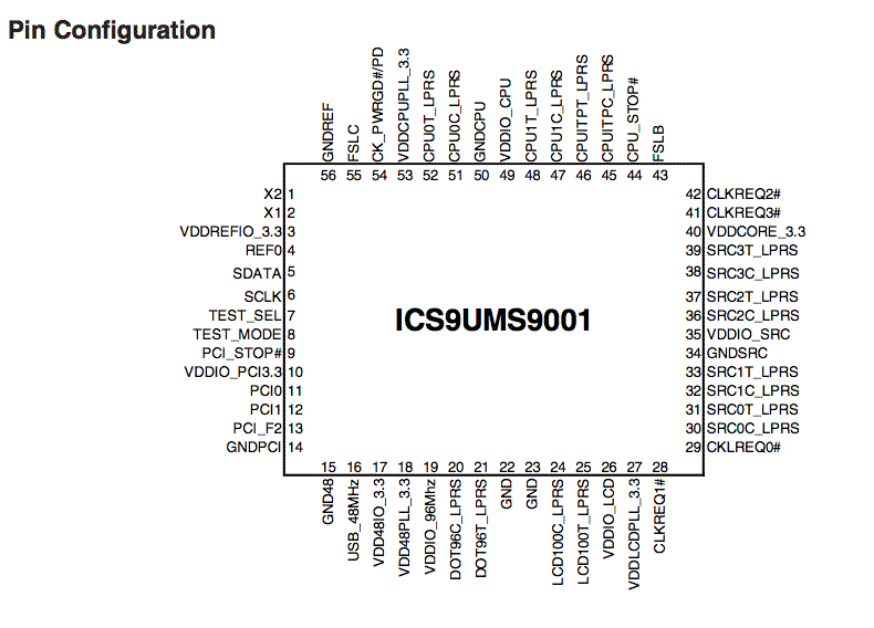
Pin 5 is SDA (data) and pin 6 is SCL (clock)
Sunspot Home. . . . . . Joggler menu
Connect to the i2c bus on the Joggler main board
WHY?
Create push button inputs, light external LED's, measure analog voltages,
run an LCD panel, control a servo motor, control the world . . . .
HOW?
Use standard i2c chips or connect to a PIC16F877A programmed as i2c slave.
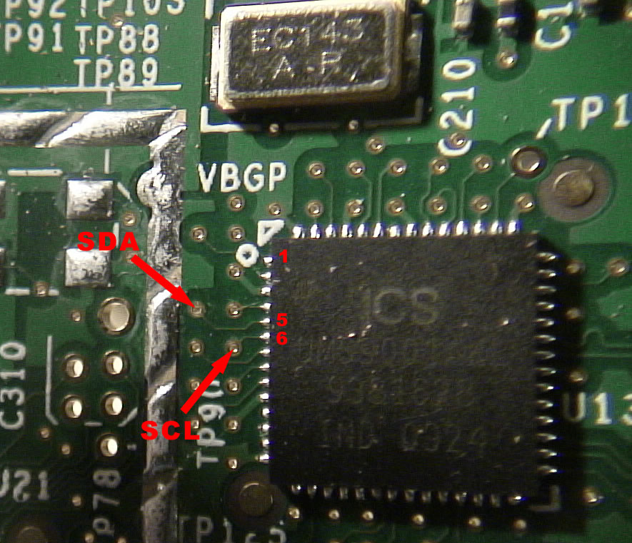
The clue to finding the bus was the ICS UMS9001 clock chip U13 - see the chip manifest (thanks)
Pin 5 is SDA (data) and pin 6 is SCL (clock)

There are 2 via's but they are too small for my soldering skills!
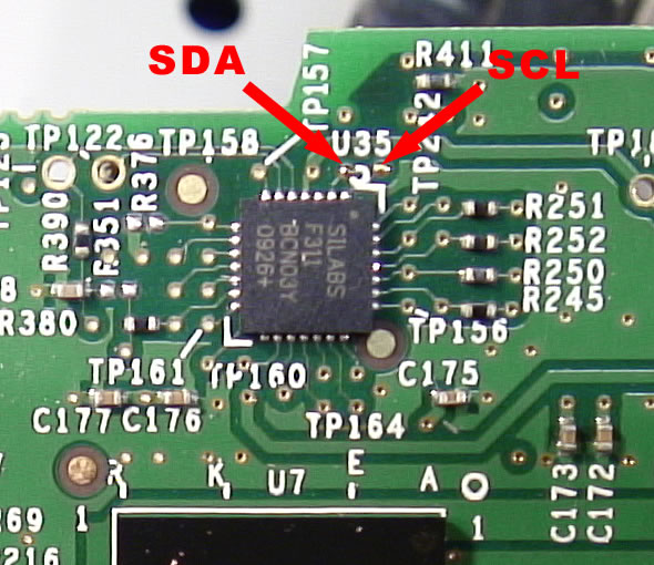
So they must also be on the 8051 type processor the SILABS F311 which is U35 (connected to the light sensor)
- the multi meter finds connections here -
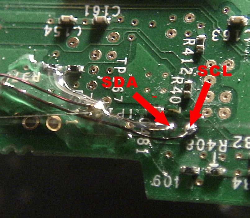
And on the back of the board behind the F311 there is just enough room to solder 2 wires
- I chose coil winding wire thin enough to enter the via ( a good anchor for the solder)
Then I used hot glue to hold the wires in place.
SCL is a bigger pad under the figure "8" of "R408". SDA is next to it.
On the far left of the board there is a copper antenna with no driver chips populated (for Bluetooth?)
I hacked this to make pads to connect the thin wires to a ribbon cable that leaves the Joggler via a hole drilled in the back.
I was unsure where to take the 3.3 Volts from and could not find a large pad to solder to.
Tell me if you locate one!
I will generate 3.3 V from the 5 V that I need for the level changer.
Earth was taken from the remains of the Bluetooth (?) antenna
Looking at the end of my ribbon cable - it seems we have a clock and some data when I enter
i2cdetect 0
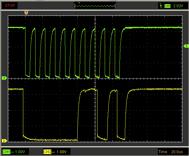
So the clock frequency is about 87 KHz
NEXT
I plan to build a level changer, an i2c long line driver and add a PIC for general purpose I/O, AtoD, model servo driver etc
- more later
- email me here if you find out more
A 3.3V to 5V i2c level converter MUST BE USED : -
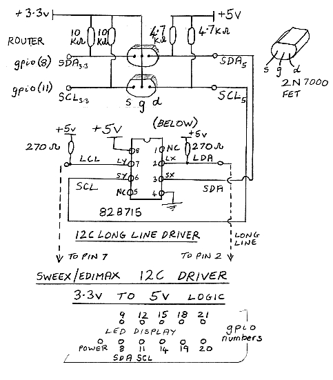
This was for my Sweex box
- I will change this for a full circuit of my PIC "breakout box" when finished
PCF8574 (8 line general purpose I/O) - WORKING!
i2cdetect 0 shows that my chip is at address 0x27 (decimal 39)
I send
i2cset -y 0 0x27 0x0 0x01 b
i.e. on i2c bus 0 at address 0x27 at the first register (there is in fact only one)
send a byte 00000001 and so set the line zero of the 8 I/O lines to high
-y "means do not ask for confirmation", b means "use binary mode"
See the man page here
I see that 0x4c is used in the Joggler
- the PCF8591P AtoD chip on my i2c test board also uses that - change then test
To read the 8 lines on a PCF8574
i2cset -y 0 0x27 0x0 0xFF b - to make all lines high as they must be before a read
- set the line states from the external devices - then -
i2cget -y 0 39 - this prints the result (note it is happy to use either decimal 39 or the equivalent hex 0x27)
Drive an external PIC16F877A using just i2cset and i2cdetect on the Joggler - a test example
The PIC has an array buffer[0x10] and i2cset can load values into it by sending the array element number followed by the value
The circuit is like the left hand circuit at the bottom of this page
e.g. i2cset -y 0 80 0 2 b sends to i2c bus 0 at address decimal 80 and places a value 2 in the array element buffer[0]
In this test pin DO is wired to an LED (then to resistor to ground - so LED on = high )
buffer[0] . . . Set the mode of action. If it is 1 then the LED flashes and if it is 0 the LED is on or off
buffer[1] . . . For the flashing mode 200 means set pin D0 high for 200 milliseconds
buffer[2] . . . For the flashing mode 200 means set pin D0 low for 200 milliseconds
buffer[3] . . . For the on or off mode, 1 means ON, 0 means OFF
CCS-C code for the PIC #include <16F877.h> // defined address 0xA0 becomes 0x50 (decimal 80) in "i2cdetect 0" display //-------------------------------------------------------i2c interupt routine if(state < 0x80) //Master is sending data if(state == 2) //Save second received byte in location buffer[address] //---------------------------------------------------------set startup state buffer[0] = 1; //----MODE 1 --continuous pulses on D0 enable_interrupts(INT_SSP); do }
|
I would like to fill the buffer array all in one stream of data but my c programs that do that for the NSLU2/Slug
SWEEX and Bifferboard compile in the Joggler and seem to run but there is no i2c bus activity as seen on a 'scope
HELP APPRECIATED
Sunspot Home . . . . . . . Joggler menu