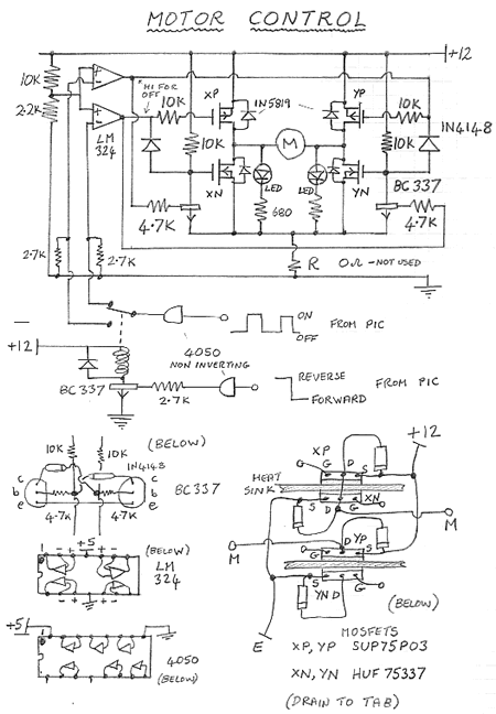
Motor Control H-Bridge power control circuit
 |
NB
Progress so far
The circuit is an
H-Bridge using a pair of P-Channel and pair of N-Channel MOSFETS. A variable mark to space pulse train is generated by a PIC Micro to control the speed. The diodes IN5819 may not be needed since the MOSFETs have internal diodes. (belt and braces!) The LM324 drives the MOSFETS hard to +12 or hard to 0 - (a transistor with resistor in the collector lead does not pull the line up hard to +12 and so properly turn off one of the P-channel MOSFETS) The 4050 buffers are to protect the PIC outputs. The MOSFETs can drive over 70 amps - my motor pair takes about 30 amps when stalled so I have not included a current limiter based on a voltage generated across R - so it is zero here. It is very important to to make sure that only one opposing pair of MOSFETs conduct at once so a relay is used to switch direction. It is only on during the reverse phase.
|
Converting
a servo pulse to a PWM pulse train for motor speed control
zero to full power over full lever range (1 to 2 msec)
' servopulse_in_PMW_out1.bas
(Oshonsoft Basic)
' PIC16F877A 4MHz
' servo pulse in to control motor power
' connect RC receiver output channel to D4, pin 27
' PMW pulse train out of CCP2(RC1) (+pulse from +veryshort to full +5V DC
out)
' use this to feed the rear wheels H-bridge power switch
' (short + pulse= low power, +5DC = full power)
AllDigital
' this assumes the HD44780 LCD is connected to
' port B as in the palmelectronics EVA board - all defaults assumed
TRISC = 0 ' all port C outputs - for CCP1(RC2) and CCP2(RC1)
TRISD.4 = 1 'set D4 as input - servo pulses into port D.4
Dim servo_pulse_length As Byte
Dim pwm_value As Word
Lcdinit 'no curser
loop:
ServoIn PORTD.4, servo_pulse_length 'measure the pulse width (1 msec = 100)
pwm_value = servo_pulse_length * 11 - 1090 'adjust to get 0-1023 from full
servo range
If pwm_value > 2000 Then pwm_value = 0 'allow for overflow pulse flip
If pwm_value > 1023 Then pwm_value = 1023 'allow for overflow pulse flip
Lcdcmdout LcdClear
Lcdout "Servo in ", #servo_pulse_length
Lcdcmdout LcdLine2Home
Lcdout "PWM out ", #pwm_value
WaitMs 4
PWMon 2, 1 ' PWM out on CCP1 (pin17), mode 1:10bit, 244Hz for 4MHz clock xtal
PWMduty 2, pwm_value ' set the duty cycle - 0 = off, 1023 = full on +5V
Goto loop
zero
to full power over half lever range (1 to 2 msec)
stick forward for motor forward
stick
back for motor reverse
' servopulse_in_PMW_2way1.bas
(Oshonsoft Basic)
' PIC16F877A 4MHz
' servo pulse in to control motor power
' channel 3, left control, push for forward, pull back for reverse
' servo values 187 max, 105 min, center 145, set dead band 140 to 152
' connect RC receiver output channel to D4, pin 27
' PMW pulse train out of CCP2(RC1)
' use this to feed the rear wheels via H-bridge power switch
' (short + pulse= low power, +5DC = full power)
AllDigital
' this assumes the HD44780 LCD is connected to
' port B as in the palmelectronics EVA board - all defaults assumed
TRISC = 0 ' all port C outputs - for CCP1(RC2) and CCP2(RC1)
TRISD.4 = 1 'set D4 as input - servo pulses into port D.4
TRISD.0 = 0 'set D0 as output - use to reverse the H-Bridge (HI = reverse)
Dim servo_pulse_length As Byte
Dim pwm_value As Word ' value from 0 (off) to 1023 (on)
Lcdinit 'no curser
loop:
ServoIn PORTD.4, servo_pulse_length 'measure the pulse width (1 msec = 100)
If servo_pulse_length > 139 And servo_pulse_length < 153 Then
' force zero in the dead band
pwm_value = 0
PORTD.0 = 0 ' set forward (keep the relay off to save power)
Endif
' push lever forward - go forward
If servo_pulse_length > 152 Then
pwm_value = 1023 * (servo_pulse_length - 152) / 35
'adjust to get 0-1023 from center to full forward on servo throttle lever
PORTD.0 = 0 ' set forward (relay off)
Endif
' push lever backward - reverse the motor
If servo_pulse_length < 140 Then
pwm_value = 1023 * (140 - servo_pulse_length) / 35
'adjust to get 0-1023 from center to full backward on servo throttle lever
PORTD.0 = 1 ' set backward
Endif
If pwm_value > 2000 Then pwm_value = 0 'allow for overflow pulse flip
If pwm_value > 1023 Then pwm_value = 1023 'allow for overflow pulse flip
Lcdcmdout LcdClear
Lcdout "Servo in ", #servo_pulse_length
Lcdcmdout LcdLine2Home
Lcdout "PWM out ", #pwm_value
WaitMs 4
PWMon 2, 1 ' PWM out on CCP1 (pin17), mode 1:10bit, 244Hz for 4MHz clock xtal
PWMduty 2, pwm_value ' set the duty cycle - 0 = off, 1023 = full on +5V
Goto loop