home
NSLU2 (Debian Slug) driving a PIC microprocessor as an i2c slave

With an i2c long line driver the i2c bus can extend for 100metres or more.
The Slug has no second rs232 port but several web sites say i2c slave mode for a PIC is difficult.
However this site
explains how to do it - (many thanks!)


This introduced me to the hardware slave mode in the 16F690
- I was then pleased to find that my favourite PIC, the 16F877A also has the mode built in

Objective -
Control a PIC microprocessor by connecting it as an i2c slave to the Debian Slug i2c bus.
Use the PIC to control model servos - and all the other things a PIC can do.

As a first test I set up to drive two model servos and also detect the state of a switch on one of the PIC pins.
(Tip - use i2cdetect to find the PIC on the bus - Linux bit shifts the expected address and that can be very confusing!)

The CCS-C code for the PIC 16F690 (but also see § at bottom of page)
(I have yet to understand the tris lines - they seem to be ignored)

#include <16F690.h>
#use delay(clock=4000000)
#fuses NOWDT, HS, PUT, NOPROTECT, BROWNOUT, MCLR, NOCPD
//------------------------PICi2cSlave.c--------------------------------
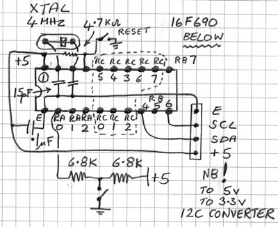
#use i2c(SLAVE, SDA=PIN_B4, SCL=PIN_B6, address=0xA0, FORCE_HW) // I2C by Hardware
//--------------------------------------------------------------------
// PORTB.4 [RB4 pin13] -> I2C SDA (I2C Serial Data)
// PORTB.6 [RB6 pin10] -> I2C SCL (I2C Serial Clock)
// defined address 0xA0 becomes 0x50 (decimal 80) on the Slug driver
// - linux puts a 0 before the i2c address and removes one at the end
//--------------------------------------------------------------------
BYTE incoming, state; // I2C vars
BYTE address ; // Address
INT16 buffer[0x10]; //Array of Int16s
INT16 DelayUsec1 , DelayUsec2 ; //delay 1000 to 2000

#INT_SSP
void ssp_interupt ()
{
state = i2c_isr_state();

if(state < 0x80) //Master is sending data
{
if(state == 0)
{
}
if(state == 1) //First received byte is address
{
incoming = i2c_read();
address = incoming;
}

if(state == 2) //Second received byte is data
{
incoming = i2c_read();
buffer[address] = incoming;
}

if(state == 3) //Third received byte is data
{
incoming = i2c_read();
buffer[address + 1] = incoming;
}
}
if(state == 0x80) //Master is requesting data
{
i2c_write (input(PIN_A0));

DelayUsec1 = buffer[address]*10;
DelayUsec2 = buffer[address + 1]*10;

}
}
//--------------------------------------------------------------------
void main()
{
delay_ms(200); // power up delay
setup_comparator(NC_NC_NC_NC);
setup_vref(FALSE);
set_tris_A ( 0b11111111 ); // Port A 11111111
set_tris_B ( 0b01111111 ); // Port B 01111111
set_tris_C ( 0b11111111 ); // Port C 11111111

enable_interrupts(INT_SSP);

enable_interrupts(GLOBAL);

{

//replace SERVO_CONTROLx by the chosen pin in all that follows the next 2 lines
#define SERVO_CONTROL1 pin_C0
#define SERVO_CONTROL2 pin_C1

//servo needs 1000 to 2000 microseconds - (actually about 500 to 2400 on my servo)
//the Slug sends about 100 to 200 which is multiplied by 10

do
{
output_high(SERVO_CONTROL1);
delay_us(DelayUsec1);
output_low(SERVO_CONTROL1);

output_high(SERVO_CONTROL2);
delay_us(DelayUsec2);
output_low(SERVO_CONTROL2);

delay_ms(10);
} while(TRUE);

}
}
//--------------------------------------------------------------------


The CCS-C code for the PIC 16F877A
-just change the i2c pins to SDA=C4 and SCL=C3

(I have yet to understand the tris lines - they seem to be ignored)


#include <16F877A.h>
#use delay(clock=20000000)
#fuses NOWDT, HS, PUT, NOPROTECT, BROWNOUT, NOCPD
//changes from 16F690 version - remove fuse MCLR
//different SCL and SDA lines - see data sheet
//------------------------PICi2c16F877_1.c--------------------------------
#use i2c(SLAVE, SDA=PIN_C4, SCL=PIN_C3, address=0xA0, FORCE_HW) // I2C by Hardware
//--------------------------------------------------------------------
// PORTC.4 [RC4] -> I2C SDA (I2C Serial Data)
// PORTC.3 [RC3] -> I2C SCL (I2C Serial Clock)
// defined address 0xA0 becomes 0x50 on the Slug driver
// - linux puts a 0 before the address and removes one at the end
//--------------------------------------------------------------------
BYTE incoming, state; // I2C vars
BYTE address ; // Address
INT16 buffer[0x10]; //Array of Int16s

INT16 DelayUsec1 , DelayUsec2 ; //delay 1000 to 2000
#INT_SSP
void ssp_interupt ()
{
state = i2c_isr_state();

if(state < 0x80) //Master is sending data
{
if(state == 0)
{
}
if(state == 1) //First received byte is address
{
incoming = i2c_read();
address = incoming;
}

if(state == 2) //Second received byte is data
{
incoming = i2c_read();
buffer[address] = incoming;
}

if(state == 3) //Second received byte is data
{
incoming = i2c_read();
buffer[address + 1] = incoming;
}
}
if(state == 0x80) //Master is requesting data
{
i2c_write (input(PIN_A0));

DelayUsec1 = buffer[address]*10;
DelayUsec2 = buffer[address + 1]*10;

}
}
//--------------------------------------------------------------------
void main()
{
delay_ms(200); // power up delay
setup_comparator(NC_NC_NC_NC);
setup_vref(FALSE);
set_tris_A ( 0b11111111 ); // Port A 11111111
set_tris_B ( 0b01111111 ); // Port B 01111111
set_tris_C ( 0b11111111 ); // Port C 11111111
set_tris_D ( 0b11111111 ); // Port D 11111111

enable_interrupts(INT_SSP);

enable_interrupts(GLOBAL);

{

//replace SERVO_CONTROL by the chosen pin in all that follows the next line
#define SERVO_CONTROL1 pin_D4
#define SERVO_CONTROL2 pin_D5

//servo needs 1000 to 2000 microseconds
//the Slug sends 100 to 200

do
{
output_high(SERVO_CONTROL1);
delay_us(DelayUsec1);
output_low(SERVO_CONTROL1);

output_high(SERVO_CONTROL2);
delay_us(DelayUsec2);
output_low(SERVO_CONTROL2);

delay_ms(10);
} while(TRUE);

}
}
//--------------------------------------------------------------------


The C code for the Slug
(compile on the slug
gcc -o 16F690test3 16F690test3.c)

Terminal -
Slug51local:/home/graham/i2c# ./16F690test3 80 0 200 100
PicData = 1
<<<switch pin AO HIGH to LOW>>>
Slug51local:/home/graham/i2c# ./16F690test3 80 0 200 200
PicData = 0

/*
16F690test3.c
------------------------------

1) send the i2c address
2) send buffer address
3) send data for buffer (address)
4) send data for buffer (address + 1)
4) print a byte that is then received from the PIC
usage :- type with spaces but without the < >
<16F690test1> <i2c address as decimal(80)> <buffer address> <data for buffer[address]>
<data for buffer [address+1]>
*/

#include <stdio.h>
#include <stdlib.h>
#include <sys/ioctl.h>
#include <fcntl.h>
#include <unistd.h>
#include <linux/i2c-dev.h>
#define I2C_SLAVE 0x0703 /* Change slave address */

int i2c;
int BufferAddress; /* which buffer[] to hold start of data */
int DataForBuffer1; /* value for the buffer[BufferAddress] */
int DataForBuffer2; /* value for the buffer[BufferAddress+1] */
int PicData; /* byte sent by PIC*/
unsigned char buf[2]; /* 3 bytes - use to feed the i2c driver */
unsigned long address; /* i2c bus address */

int rc;

int main(int argc, char** argv)
{
if (argc != 5) /* report error if we are not getting just 4 inputs after the program name */
{
printf("Error. usage: %s i2c_chip_address BufferAddress data_for_buffer[address] data_for_buffer[address+1]\n", argv[0]);
}

address = atoi(argv[1]); /* i2c decimal address is the first number after the program name */
BufferAddress = atoi(argv[2]); /* the array number for buffer */
DataForBuffer1 = atoi(argv[3]); /* data for buffer[BufferAddress]*/
DataForBuffer2 = atoi(argv[4]); /* data for buffer[BufferAddress+1]*/

i2c = open("/dev/i2c-0",O_RDWR); /* open the device dev/i2c-0 */
rc=ioctl(i2c,I2C_SLAVE,address); /* set the i2c chip address */

buf[0] = BufferAddress; /* address in buffer to start recording received data */
buf[1] = DataForBuffer1; /* second data byte to be sent */
buf[2] = DataForBuffer2; /* third data byte to be sent */
write(i2c,buf,3); /* we send 3 bytes <BufferAddress> <DataForBuffer1> <DataForBuffer2>*/

/* the next command forces the PIC to respond - it makes "(state == 0x80)" in the PIC */
read(i2c,buf,1); /* buf(0) now contains 1 data byte from PIC */

PicData = buf[0];

printf("PicData = %d \n", PicData);

i2c = close(i2c);
return(0);
}


(This is "Lesson 1, Copy, Paste and Pray C code" - do not use it to control a lift )

Matrix board layout for the 16F690

- seen from below - the solder side.
(I also attached a socket matrix project board for this test)


The 'scope output from the 16F877A

Slug51local:/home/graham/i2c# ./16F690test3 80 0 100 200
(The same Slug code drives PICs 16F690 and 16F877A)


PIC 16F877A as i2c slave printing to 4x20 LCD display and rs232

I have learned how to get the Slug to send bytes to the PIC and have the PIC send two byte AtoD numbers back to the Slug
These files are for my backup but there are lots of comments if you learning with me.

16F877_AD_rs232_LCD_i2c_5.C CCS PIC program for 16F877A

PIC_i2c.c Slug driver program

Flex_LCD420.c my backup copy of this driver (with thanks!) with my settings to work with the above

more detailed notes are here


§ No need to buy CCS C compiler for PIC i2c slave code?
I thought that CCS was the only compiler that helped you use a PIC as i2c slave.
I have now discovered that the free JAL compiler has been used to do that - I have not tested it yet

See http://www.lightbullet.com/download.php and Google for JAL
perhaps also
http://www.sirloon.net/loonaweb/sirblog/i2c-com-with-two-16f88-master-slave