
more notes for backup and a bad memory - -
BEWARE- Lesson 1 programmer. . . .
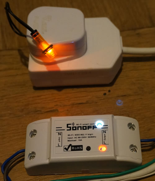
Reprogram a Sonoff power switch for use on my home LAN
Objective - Control mains powered devices using verbal commands to Amazon Alexa
Many thanks to Pete Scargill for all the information
MQTT is still on my "learn about it soon list" so I used the web page control method as in the Arduino example sketches.
For Alexa verbal control see the blue text in the Python code here .
I also learned how to use an interrupt to get the relay to toggle under manual control (the main loop in the sketch does not loop if there are no http commands) .
I have a white LED in series with 1Kohm wired across the relay coil (they are very bright these days and the 1Kohm could be increased).
I connected gpio14 via 1Kohm to the red LED in the two colour LED. The centre pin of that LED goes to 3.3V. See photos below.
The bare wire on the antenna side of the LED goes to the red light. The light source was on the side of my LED, not under the focus, so it was not very bright. I suspect Sonoff are using up half faulty LEDs in the non radio versions! I cut the wire on the LED but that is not essential since many components used for radio control are missing.
I used an external 3.3 volt supply for testing since I had trouble on another project with the weak 3.3 volt supply in my USB serial link
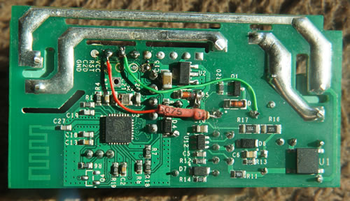
I found that the solder pad on the push button ( the one that is not at the board edge but near the gpio strip )
connects directly to gpio0 via zero ohms. I had wondered if it could be used as an output pin but the push button would have to removed in case a button push shorted a high gpio0)
Anyway -I need the button!
The ESP8266 sketch below is loaded by the Arduino IDE
!!!!! NB only use mains power when all testing is done and the box is closed !!!!!
/* NB! - this is the Sonoff device with no radio remote control components #include <ESP8266WiFi.h> // from a terminal or bash script send one of - const char* ssid = "my WIFI SSID"; //'''''''''''''''''''''''''''''''''''''''''''''''''''''''''''''''''''''''''''''''''''''' for Interrupt // Interrupt Service Routine (ISR) // Create an instance of the server // prepare GPIO12 // prepare GPIO13 // prepare GPIO14 //'''''''''''''''''''''''''''''''''''''''''''''''''''''''''''''''''''''''''''''''''''''' for Interrupt // Connect to WiFi network WiFi.begin(ssid, password); while (WiFi.status() != WL_CONNECTED) { // Start the server // config static IP // Print the IP address //======================================================== loop start // Wait until the client sends some data // Read the first line of the request // Match the request if (req.indexOf("(00)") != -1) //not equal to -1 means it was present if (req.indexOf("(20)") != -1) if (req.indexOf("(30)") != -1) Serial.print("old_val0 = "); Serial.println(old_val0); old_val0 = val0; // relay //else { if (val0 == 1) // Set GPIO according to the request client.flush(); // Prepare the response // Send the response to the client if (val2 == 0) { client.print("the green LED is on <BR>");} if (val3 == 0) { client.print("the red LED is on <BR>");} delay(1); // The client will actually be disconnected |
Drive the red lamp in the red/green LED - 1 Kohm to gpio14
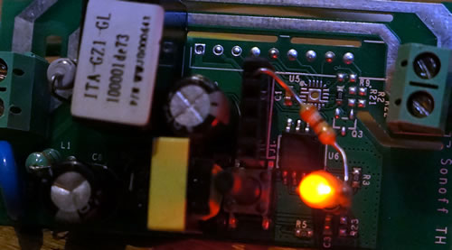
The white LED connected to the relay coil
Use the radio pins to send signals to the other side of the board
- the white LED and 1Kohm series resistor connect to the relay coil
Please email me if you want to swap notes